
Planning
 The planning process begins with the selection of the ship to be constructed. Ideally we look for clear photographs and drawings, particularly plans and elevations.
It may well be that the plans and photographs are of different dates, however the basic hull shape and elevation are unlikely to change in proportion (unless there is a major conversion for a change of use).
Using both the internet (Wikipedia and general images) and reference books (the Ian Allen series, Janes fighting ships etc) we can collect a series of images and select those which give specific information – the bridge, funnels, cranes, armament, close ups of other features, general scale views, aerial views, views beam on, from ahead and astern.
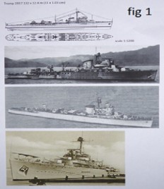
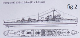
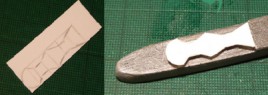
Scaling is important and can help when construction begins. In fig 1 a plan and elevation have been taken from the internet. It is worth checking the plans alongside photographs to ensure that the relative scale is correct. In fig 1 we can see that the plan has been sized so that the printed page gives a plan exactly to the scale 1:1200. This saves a lot of time during construction. It may be useful to have the plan to scale and also the plan enlarged to identify small features more easily. To work out the size of the scaled image we use the following formula:
Length of ship in metres / 12 = Length of scale model in cm
Or Length of ship in feet x .0254 = Length of scale model in cm
 Using the rulers on your computer screen you can then adjust the size of the image on the printed page. If this is not exact then print a page of images from slightly smaller to slightly larger on the same page and use the one which matches the size most precisely. You have now completed a page or several pages which describe the model you intend to make precisely. Remember you can go back to your sources for further information.
Materials
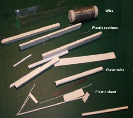 You need to look at the materials you will use. The list is endless but the first on any list would be balsa wood, particularly for the larger parts of the hull and superstructure depending on the overall size of the model. This will be in sheet form of thickness 1, 2, 3, 4 or 5 mm.
 In addition it is possible to purchase plastic strip with different cross sections – round, square, L, H and I shapes, rectangular. Having a variety of these available makes good sense and over the period of your modelling you will build up a variety of these. The smallest need to be around .25 mm up to 5 or more mm, generally tube.
For masts, gun barrels it is possible to use wire, either soft modelling wire or phosphor bronze – old guitar strings are good, however, If using this you will need special pliers to cut it and should be careful as the pieces tend to fly. These types of wire are very thin and quite difficult to handle.
We may also use paper, the best being from colour magazines because of the high quality, which can be used as an alternative to paint in some circumstances. Finally you will be able to buy beads and sequins of different sizes and hole punches to create circular objects in thin paper and plastic.
Tools
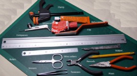 The most important is your cutting device – a scalpel – with interchangeable blades. You can buy the blades and handles separately and I would recommend having several. The blades do get blunted and should be replaced on a regular basis. Two types of glue are needed; a general universal glue and balsa cement, the former for assembling components, the latter for sealing the balsa once shaped. Most adhesives are based on solvents and care should be taken with ventilation and the period of time you work in this atmosphere. This also applies to filing and sandpapering as the dust produced can be harmful if breathed in. Metal rulers in cm and mm. larger and smaller, and tweezers, small scissors, heavy scissors, bulldog clips, small clamps, a pair of compasses, pliers and files. The sharp blades and pairs of compasses may well provide a convenient method of holding small components for painting. You are now ready to begin construction.
Hull rough cut
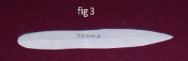 The first requirement is to produce a hull pattern from your scale plan. Firstly fold you piece of paper in half and mark out the length of the model on the folded edge.
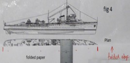 Place the folded paper with the fold along the centre line of the plan. You will have blank paper on the left side and the half hull plan on the right. At regular intervals measure the distance to the edge of the plan and transfer that distance onto your folded paper. In this way you will create and exact copy of the shape. Join the dots and cut out the shape (see fig 4). When opened out you have an exactly symmetrical pattern for the hull.
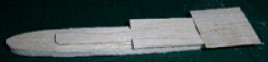
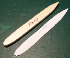 Selection of the balsa wood or plastic for the model will be done using the elevation drawing. Initially it is necessary to select a thickness which will fit the lowest continuous freeboard. Small variations can be cut in if necessary. Using the hull pattern the shape is marked out and the basic shape cut. This is the rough cut. If there is a step in the hull a second appropriate thickness needs to be cut to length but 2 mm over width.
A centre line needs to be drawn on this piece and the shape of the upper piece marked out by measuring from the plan and marking either side of the centre line and then cut. Without further cutting the upper section is glued in place (with your universal glue) and left to set for an hour or more.
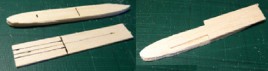
 Once set, this upper section can be cut to the shape pf the bottom section. At this point there is no vertical shaping, no shear, no stern shape. Looking from above the shape should match the shape of the pattern exactly.
Hull shaped
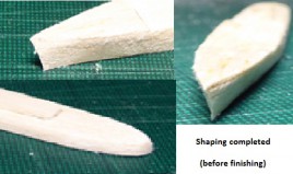 We now have to shape the bow and stern. We need to get the shear on the bow which is best done by creating the angle of the bow vertically then create the waterline shape and file or cut the bow with the curve of the deck tapering to the straighter line at the waterline. There is less curve at the stern so the angles need to be created from the elevation with a file and sandpaper.
]We have the basic shape but balsa wood has a very open grain.
To seal the grain we use balsa cement. 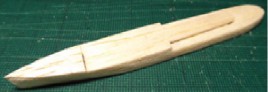 A thick layer of balsa cement should be applied and then rubbed all over until every surface is covered. The cement should soak in. Once the cement is thoroughly dry we use fine sandpaper to smooth the surface. If it is not thoroughly smooth then apply another layer and sandpaper once again. The wood will be firmer and slightly darker. When painted we should now get a good surface.
Hull finished, painted
 Now the hull can be finished with paint. If using acrylic paint we will need to use at least two coats as a single coat will not cover. Colours are a matter of preference but I will be using a dark metallic grey for the decks and a lighter grey silk for the upper-works and hull.
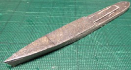
Using the deck colour we paint all of the surfaces to prime them. Once this is dry we can apply a second coat to the decks, then we paint the hull sides with two coats of the lighter grey. The final task is to repaint the decks to get a good line between the deck and the hull side. The paint should now ensure that we have a reasonable finish. If not a further sanding and coat of paint should solve the problem.
The paint we use is either enamel or acrylic. Acrylic paint is more convenient as it is easier to wash brushes as we don’t need to use solvents which are both a health hazard and contaminate.
Superstructure
 Generally the superstructure consists of several structures including the bridge, a mid-ships section where the funnels are located and an after section where the after armament may be located. These can all run into a single structure or, particularly in older vessels may well be completely separate. The base of the structure is completed in the initial hull form. It is necessary to create the deck shape which is glued on top of this, made from thin plastic sheet. It may then be painted the same colour as the deck. Now we are able to begin to complete the superstructure. We will begin with the bridge.
Bridge
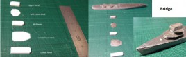 We begin constructing the bridge using 5 x 2 mm plastic section and very thin plastic sheet. The 2mm thickness on a scale of 1:1200 gives a height of 2.4m full size which corresponds to the real deck height.
Using these materials we ensure that the decks are accurately parallel, giving a realistic appearance. Cutting by hand is difficult so making the bridge in one piece is very much more troublesome. At this point we should paint the surfaces which will be in view, deck and superstructure colours. A mast is going to be located on the top of the bridge so, using compasses, a small locating hole in pressed lightly into the top section. We are now ready to assemble the bridge. Once assembled we can touch up the deck and side areas and the bridge is complete except for smaller detail which we do in the fitting out process.
Funnel
 The funnel is shaped from an 8 x 3mm plastic strip. The shape was cut out ensuring that the base of the funnel was the original straight side of the strip. This ensures that the funnel when fitted will stand upright. The end are rounded with the knife and file to create the shape. The slope of the funnel top is taken from the elevation.
Before fitting, the funnel is painted in the hull colour. It is helpful to impale the funnel on the scalpel to paint it. Make sure you impale it on the side which will be glued to avoid scarring on the visible surface. Once dry the funnel can be glued in place making sure it is lined up with the funnel on the elevation. The top of the funnel is painted black either before or after fitting.
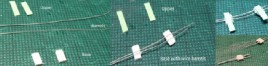
Torpedo Tubes
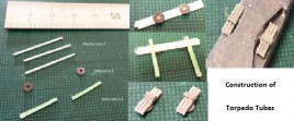 Torpedo tubes are in triple sets on Trump so we need to select three short pieces of rod of a suitable diameter, enough to make two sets of tubes (about 20mm). We select also two sequins of diameter slightly larger than the three rods together as the turn-tables. Aligning the rods parallel the sequins can be glued on top. Then turning the assembly upside down we can add to top mechanism by gluing a 1mm wide strip of thin card so that it aligns just outside the sequin. Finally the card is trimmed to size and the assembly painted grey. The tubes can now be cut to length (here 7mm) and fitted onto the deck on either side.
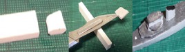
Main armament
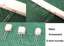 The main armament is 6 x 5.9” in 3 twin turrets. Here we will need to select a piece of plastic rod of roughly the right dimensions – 4mm x 1.5mm cross section of length 4.5 mm. The first job is to create the holes for the barrels in the strip before cutting to length. This is done with the compasses and doing it before cutting allows us to cut the plastic to the right size and still be able to hold the item. Two pieces of thin wire are then glued in place and roughly trimmed to about 1cm in length. The plastic can be cut to the right size and shape once the glue is set. Leaving the wire longer makes it easier to paint the assembly ready for installation.
Secondary Armament
 The secondary armament is 8 x 40mm AAA in 4 twin mountings with 4 20mm AAA in twin mountings.
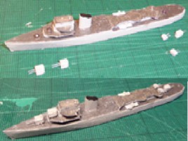 The 40mm mountings are composed of a base of plastic strip with two gun barrels of thin wire with an upper of 1mm wide thin card.
The wire is glued onto the two gun bases and then the upper is glued on the top sealing the whole assembly. Once the assembly is dry the two gun mountings can be separated by cutting the barrels to the right length. Finally the sides can be trimmed down and finished by painting. The primary and secondary armaments can then be installed on the mounts (sequins) previously glued in place.